Coaxial cable types, included antenna cables, installation and length selection
An antenna cable is the coaxial cable connecting an antenna to a router, hotspot, radio or receiver. It carries radio-frequency signals in both directions. When shopping, you will often see names such as RG58 cable, RG174 cable, SMA cable and antenna extension cable. Start by checking the cable supplied with your antenna before buying anything extra.
Most of our cable-equipped outdoor antenna products come with a cable attached or included in the package. If its length reaches your chosen location and its connectors fit your equipment, you do not need a separate antenna extension cable. This saves the cost of an additional cable and avoids another connection that can add signal loss. This guide covers cable selection first, practical uses second, and cable length and loss calculations third.
How to Choose the Right Antenna Cable
Check the included antenna cable first
Our antenna range includes cable-equipped models as well as direct-mount antennas. For cable-equipped models, check the included length, cable type, connector and number of cable paths. A bundled cable can cover the installation without a separate purchase; an extension is only needed when the supplied cable cannot reach. Direct-mount and antenna-only products may have different package contents.
 Examples follow the antenna collection listings. Verify the selected variant and package contents. Two 2 m MIMO cables provide two separate 2 m paths, not one 4 m cable.
Start with both connection points
Check the antenna connector and the equipment connector separately. RP-SMA means reverse-polarity SMA. It looks very similar to standard SMA and uses the same screw-thread arrangement, but the centre pin and socket are swapped. “Reverse polarity” describes the connector contact, not a reversed cable or a different signal direction. Look at both the threads and the centre contact before choosing a cable:


Match SMA male with SMA female, or RP-SMA male with RP-SMA female. Do not mix the two families: SMA male and RP-SMA female bring two pins together and can be damaged; RP-SMA male and SMA female bring two sockets together, leaving no proper centre contact even if the threads engage. For example, a router port with outside threads and a centre pin is RP-SMA female, so it needs an RP-SMA male cable end with inside threads and a centre socket. Also distinguish TS9 from similar small push-on interfaces rather than judging by appearance alone.
For a direct connection, both cable ends must mate with the actual ports. For an extension, one end must mate with the existing antenna lead and the other with the equipment. For example, a female SMA antenna lead and a female SMA device port require an appropriate male-to-male assembly; an existing male SMA lead and a female SMA device port can be extended with a compatible SMA female-to-male assembly.
Straight connectors work where clearance is available. A right-angle connector can reduce protrusion behind equipment, but it must point in a usable direction. Bulkhead connectors are intended for mounting through a suitable panel. Support the cable so its weight does not pull on a small router or hotspot port.
Match impedance and operating frequency
Many cellular, WiFi, LoRa and two-way-radio antenna systems use 50-ohm antenna cables. Television systems commonly use 75-ohm coax such as RG6. Confirm the actual equipment requirement: matching the connector alone does not make a 75-ohm television lead a suitable substitute for a 50-ohm radio antenna cable.
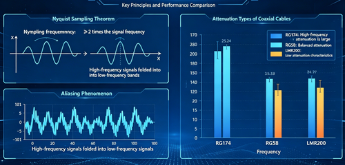
Antenna Cables are not selected by antenna frequency labels in the same way as antennas. Instead, check the finished assembly’s supported frequency range and its attenuation or insertion loss at the frequency you will use. A cable that is acceptable at 915 MHz may introduce too much loss over the same distance at 5 GHz. Connector quality and assembly construction also matter.
Choose construction for the route and loss budget
BOOBRIE lists RG316 short adapter leads, RG58 and RG58U cable assemblies, and Quad 200 multi-cable products. These provide different connection and routing options. Compare the exact product specification rather than assuming all cables with a similar name have identical electrical or outdoor performance.

*Approximate references from our published information: RG316 about 2.5 mm; RG174 2.79–2.80 mm; our 1.8 m RG58 BNC cable 5.0 mm; RG6 kit images approximately 6–7 mm. Dimensions vary by assembly. For tight spaces, check your selected model; ask us for Quad 200 individual cable and overall sleeve dimensions.
How diameter affects signal loss. At the same frequency and length, larger internal conductors generally reduce resistive loss when construction is comparable. A thicker plastic jacket alone does not improve transmission. Conductor material, insulation and shielding also matter, so diameter cannot give an exact dB loss. Thin RG174 and RG316 leads favour compact routing; neither is automatically lower-loss than the other.
How diameter affects installation. Thicker cables occupy more conduit space, usually need wider bends and place more weight on ports. Thinner cables suit small enclosures but still need protection from tension, crushing and sharp turns. Size openings for the largest connector or bundled section, not just the jacket, and follow the selected cable’s minimum bend radius.
Bend radius in practice. Never fold thin coax into a sharp crease or a tight U-turn, even when it feels flexible. For initial routing, leave room for a broad curve with a radius of about 10 times the cable outside diameter (10D), then confirm the selected cable’s minimum. At 10D, a 2.8 mm RG174 lead needs a radius of at least 28 mm, while a 5.0 mm RG58 cable needs at least 50 mm. The curve diameters are approximately 56 mm and 100 mm respectively. This is a planning example, not a universal BOOBRIE rating; the model’s specified minimum takes priority, and repeated flexing may require a larger radius.
BOOBRIE diameter references: RG316 construction | RG174 construction | 1.8 m RG58 BNC cable | RG6 extension kit
A flexible short RG316 lead can be useful next to a hotspot or enclosure. BOOBRIE’s range includes an SMA-female-to-TS9-male right-angle RG316 lead. Its role is to connect compatible interfaces; it does not amplify the signal. RG58 assemblies are available with different lengths and connector combinations, including SMA and RP-SMA extensions. Availability of a long cable does not establish that its loss will be acceptable for your particular installation.
Our Quad 200 antenna extension cables combine four independent BMR200 coaxial paths in one protective sleeve to keep compatible multi-port router installations organised. We offer SMA male-to-female versions, including a right-angle option for limited space behind equipment. Choose the connector arrangement and length for your setup, and compare each path’s loss at your operating frequency. Each antenna signal travels through its own cable.
Quick cable choice by installation
- RG174: Prioritise a compact, lightweight lead for a nearby antenna, small enclosure or desk setup when its loss is acceptable. Use an antenna’s supplied lead first if it reaches; avoid adding unnecessary extensions.
- RG58 or RG58U: Prioritise a main antenna run to a window, wall or outdoor mounting point when a thin lead would lose too much signal. If the thin cable exceeds your loss budget, a lower-loss assembly is required; RG58 is one option, provided its own specified loss is acceptable.
- RG316: Use short interface jumpers, such as the 15–50 cm adapter leads in our range. Avoid choosing it by default for a multi-metre or room-to-room run, especially at higher frequencies; a thin jumper’s compact size does not make it a low-loss long-distance cable.
Read the cable parameters before choosing a length
Cable names alone do not tell you the complete specification. For RG58, RG174 and RG316 assemblies, check nominal impedance, overall diameter, centre conductor, dielectric, shielding, jacket material, attenuation at your operating frequency and minimum bend radius. Diameter affects routing; shielding and construction affect electrical performance; jacket and temperature ratings affect where the cable can be installed.
 For an example from our own range, our 1.8 m RG58 BNC male-to-male cable lists 50 Ω impedance, an 18 AWG copper centre conductor, a 2.95 mm dielectric, a 144 × 0.12 mm tinned-copper braid with more than 95% coverage, and a 5.0 mm PVC outer jacket. Use its diameter to assess clearance. These specifications apply to this cable; check the selected assembly before applying them to another RG58 or RG58U model.
Examples of short jumpers and single-path extensions. Product-inspired illustration.
Keep MIMO antenna cables independent
A compatible 2×2 MIMO antenna installation uses two independent signal paths. An externally supported 4×4 arrangement can require four. A multi-cable assembly keeps these paths organised; it is not a one-to-four splitter and does not create additional MIMO capability in a router.
Confirm how many external cellular antenna ports the router actually supports, then label and connect each path according to its manual. Cellular, WiFi and GPS ports are not interchangeable. Use a consistent cable type and comparable path loss where the manufacturer recommends it, and evaluate each antenna cable separately.
Antenna Cable Applications and Installation
WiFi antennas on desktops and access points
A short antenna cable or extension can move a compatible antenna away from a metal computer case or an obstructed position behind a desk. Choose SMA or RP-SMA according to the actual ports. Start with the shortest route that gives useful placement flexibility, especially on higher WiFi bands. Test the new antenna position before fixing the cable permanently.
The cable connects an external antenna port; it cannot replace a USB network adapter or make a device without a supported antenna connection accept one. Avoid tight bends behind furniture and leave access to the connector for servicing.
Cellular routers and mobile hotspots
Use the antenna’s included cable first when it reaches the chosen window or outdoor position. Some kits also include a short SMA-to-TS9 adapter lead, so a compatible hotspot may not require another cable purchase. Add an extension only when the route needs it, and include every section in the loss estimate.
For multi-port routers, route every required antenna path and follow the port mapping instructions. A Quad 200 assembly may simplify cable organisation when its connectors and number of paths match the system. Compare signal quality and repeatable connection performance before and after the change; a better antenna location must provide enough benefit to justify the additional cable loss.
LoRa gateways and outdoor monitoring
An external LoRa antenna may need a antenna cable between a mast or wall position and an indoor gateway. Check the gateway’s operating band and connector requirements, then compare antenna cable loss at that band. For a camera or monitoring device, first establish whether the external port serves cellular, WiFi or another radio system.
Choose a jacket and connector arrangement rated for the actual outdoor exposure. Support the cable along its route, protect the wall entry and provide a drip loop where needed. Weather resistance of the antenna housing does not automatically make an exposed cable connection waterproof. Follow the product’s sealing instructions, and follow applicable grounding and lightning-protection requirements for elevated outdoor installations.
Two-way radio and vehicle installations
Compatible BNC or PL-259 assemblies can connect radio equipment, antennas and suitable measuring equipment. Check impedance, frequency, transmitter power and connector ratings for the complete assembly. The connector name “UHF” does not by itself establish suitability for every UHF-band installation.
In vehicles, route the antenna cable away from pinch points, moving parts and hot surfaces. Use proper feed-throughs rather than crushing a cable in a door or window. Secure the route without over-tightening cable ties. Check the antenna system according to the radio manufacturer’s procedure before transmitting.
Example placement scene with the coaxial antenna cable as the main subject. Confirm actual equipment and connector compatibility before installation.
Installation checks that apply to every scenario
Handle connectors by their bodies, align them carefully and use the manufacturer’s tightening method. Do not force a mismatched connector or twist the cable to tighten a threaded coupling. Observe the specified minimum bend radius and avoid sharp kinks, crushing and tension. Inspect exposed connections and cable jackets periodically for damage or moisture.
If performance worsens after adding a antenna cable, check loose connectors, incorrect centre contacts, wrong port assignment, water ingress and excessive length. Simplify the connection path where practical and test with a known compatible short assembly. A passive antenna cable cannot compensate for an incompatible antenna or unsuitable antenna position.
How to Choose the Antenna Cable Length
Measure the actual cable route
Choose the antenna position first, then measure the route to the equipment with a flexible tape or string. Include bends, walls, mounting supports, entry points and connector clearance. Allow enough slack for gentle bends and maintenance without adding unnecessary loops. The straight-line distance is usually shorter than the installed route.
Length is a routing decision, not a universal performance recommendation. A 50-centimetre jumper may suit nearby equipment; a 3-metre or 5-metre assembly may suit a longer route only if its loss is acceptable. A route measuring 4.6 metres could fit a 5-metre assembly after checking usable length, slack and tolerances. Do not select 10 or 15 metres merely because the extra cable might be convenient later.
Count the complete antenna cable path
Include the cable already attached to or bundled with the antenna. If a 5 m supplied cable reaches a 4.6 m route with enough slack, use it without buying an extension. A 5 m supplied cable plus a 3 m extension creates an 8 m path and an extra mating connection. Calculate each section separately when cable types differ, and repeat the calculation for every MIMO path.
Estimate loss at the frequency you actually use
For an approximate cable-only calculation, multiply the specified attenuation per metre by the cable length. For mixed cable types, add the loss of each section. Include additional connector or adapter losses only when they are not already included in a finished assembly’s insertion-loss specification.
A practical rule for higher-frequency links. For 5 GHz WiFi and higher-frequency cellular 5G bands, keep the complete RF cable path as short as the installation allows. Avoid long room-to-room extensions and coils of spare cable. Higher frequency usually means more loss over the same cable length, so even RG58 may be too lossy for a long run. “5G” names a mobile-network generation; it does not mean every 5G connection uses 5 GHz.
Cable loss (dB) = attenuation (dB/m) × cable length (m)
If a specification uses dB/100 m, divide by 100 to obtain dB/m. If it uses dB/100 ft, divide by 30.48. For multiple cable sections, total path loss = Σ[section attenuation × section length] + additional connector and adapter losses. Do not add connector loss again if it is already included in the assembly insertion-loss specification.
Worked cable loss example
Assume, for calculation practice, that a cable has attenuation of 0.5 dB/m at the operating frequency. This is an illustrative assumption, not a measured BOOBRIE RG58, RG174, RG316 or BMR200 specification. The table excludes connector losses.

Power remaining (%) = 100 × 10^(−loss in dB / 10). Extending the assumed 5 m cable by 3 m adds 1.5 dB: about 70.8% of the power available before that extension remains after it. This is an RF power calculation; internet speed does not decline by the same percentage.
For a mixed-cable example, assume the 5 m main cable loses 0.5 dB/m, the 0.15 m jumper loses 1.0 dB/m, and additional connections contribute 0.2 dB in total. Path loss = (5 × 0.5) + (0.15 × 1.0) + 0.2 = 2.85 dB. All attenuation and connection values in this example are assumed; replace them with specifications at the same operating frequency.

For a stated cable-only loss budget, maximum length (m) = allowed cable loss (dB) ÷ attenuation (dB/m). A 3 dB cable budget at the assumed 0.5 dB/m gives 6 m. Subtract adapter and connector losses from the total path budget first. Higher-frequency bands usually require a tighter length check; do not reuse a 900 MHz attenuation value for 5 GHz.
If the planned loss is too high, shorten the route, place the radio equipment closer to the antenna, or choose a verified lower-attenuation assembly. In suitable installations, moving network equipment closer and extending Ethernet can avoid a long radio-frequency cable run. Check power, weather protection and network requirements before making that change.
Final selection checklist
- Both cable ends mate with the actual antenna and equipment interfaces.
- Impedance, frequency range and power rating suit the system.
- The exact cable construction provides acceptable loss over the complete route.
- Every required MIMO path remains independent and connects to the correct port.
- The jacket, exposed connections and entry points suit the environment.
- The cable reaches without tension and can follow the required bend radius.
- Performance has been checked before the installation is made permanent.